


SSD Form Factors
Click on the names below to learn more about the many different SSD sizes and formats in a variety of form factors. Images of the form factors are provided by CMSI member companies.
NVMe SSDs service many use cases in the data center. The NVMe SSD Classification page shows the different types of NVMe SSDs for different hyperscale and enterprise use cases.
The SNIA SFF Technology Affiliate (SFF TA) is developing a broad range of standards for new connectors, form factors, and transceivers. They were the recipients of the 2024 FMS Best of Show - Most Innovative Memory Technology Award.

Richelle Ahlvers, Anthony Constatine, Paul Coddington, Mike Allison, and Lee Prewitt accepting the FMS 2024 Best of Show Award
And for the latest on EDSFF form factors, view this video on The Latest in Form Factors and download new white papers written by SNIA members Dell, HPE, KIOXIA, Meta, and Microsoft.

EDSFF
EDSFF stands for Enterprise and Datacenter Standard Form Factor. The family of specifications were developed by a group of 15 companies working together to address the concerns of data center storage, and are now maintained by SNIA as part of the SFF Technology Affiliate Technical Work Group (SFF TA TWG).
EDSFF offers a dynamic range of form factors that have advantages vs the incumbent SSD form factors in capacity, scalability, performance, serviceability, manageability, thermal and power management. Today all the EDSFF family of form factors share the same protocol (NVMe), the same interface (PCIe® ), the same edge connector (SFF-TA-1002), the same pinout and functions (SFF-TA-1009). Infrastructure, especially test infrastructure, can be developed to support multiple EDSFF form factors. Learn more about the EDSFF family.
EDSFF and CXL
EDSFF E1.S, E3.S, and E3.L form factors, as well as AICs, have been integrated into the Compute Express Link® (CXL®) ecosystem, underscoring their utility in high-performance, high-capacity server environments promoting robust, scalable, and efficient designs. This adaptability makes these form factors critical components in the evolution of data center hardware, accommodating both traditional storage and advancing memory technologies like CXL.
The JEDEC Memory Module (CMM) Reference Base Standard – for Compute Express Link (CXL) (JESD317A) defines the specifications of interface parameters, signaling protocols, environmental requirements, packaging, and other features as a reference for specific target implementations of CXL-attached memory modules. The purpose is to simplify system design, ensure source multiplicity, eliminate confusion, and ease device specification and use.
JESD317A key references and standards include:
- PCI Express® (PCIe) Base Specification and PCIe Card Electromechanical Specification
- Compute Express Link Consortium: CXL Specification
- SNIA SFF-TA-1002, SFF-TA-1006, SFF-TA-1008, SFF-TA-1009, and SFF-TA-1023
- SNIA Specifications covering everything from the card edge connectors to thermal characterization for EDSFF Devices
- JESD405-1 JEDEC® Memory Module Label – for Compute Express Link® (CXL®)
E1.L, EDSFF 1U Long
E1.L is a form factor that was developed to maximize capacity per drive and per rack unit in a 1U server or storage array (JBOD, JBOF), with superior manageability, serviceability, and thermal characteristics vs traditional form factors that were designed for rotating media. There are options for x4 or x8 lanes of PCIe while fitting vertically in a 1U chassis to allow for scalable bandwidth per drive, as well as options for 9.5 or 18mm heat sinks for various power and thermal environments (25W and 40W respectively). It improves data center serviceability, and is designed to be hot pluggable and front access serviceable with LEDs built into an integrated enclosure.
Use Cases
E1.L is optimized for high-capacity and dense storage use cases. High capacity per rack unit can improve data center TCO by offering storage consolidation and more power efficient storage (TB/W).
Dimensions
Mechanical/Electrical Specification
Connector Specification
Protocol
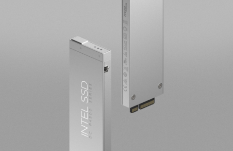
E1.S, EDSFF 1U Short
E1.S is a flexible, power-efficient building block for hyperscale and enterprise compute nodes and storage, as well as for Compute Express Link (CXL) memory modules. The M.2 110mm form factor was popular in hyperscale data centers due to its low-cost structure, flexibility, and scalability of multiple drives per server. However, it faced challenges in terms of hotplug/serviceability, thermals and overheating, and scaling to high capacities. E1.S addresses these issues while maintaining a small form factor. It is slightly longer but wider than M.2, designed to accommodate more media (NAND) packages for increased capacity per drive. It fits vertically in a 1U chassis, similar to E1.L, enhancing serviceability and cooling efficiency.
The specification for E1.S 5.9mm includes four standard mounting holes for heat sinks or carriers, ensuring improved thermal management. Different variants of E1.S offer enhanced flexibility for power, performance, scalability, and thermal efficiency. The latest version of E1.S features a new optional symmetrical enclosure of 9.5mm width (similar to E1.L) that allows scalability up to 20W and x8 PCIe if required. While mainstream SSDs utilize PCIe x4, the form factor's support for PCIe x8 enables the use of other devices requiring higher bandwidth. The 15mm and 25mm asymmetrical enclosures provide a trade-off: fewer drives per rack unit but improved power and performance per drive. At similar power levels, these enclosures offer better cooling and thermal performance, reducing the required airflow.
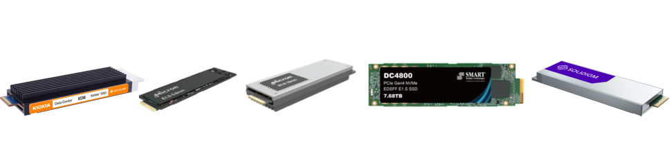
Illustrations left to right: E1.S (courtesy of KIOXIA); E1.S 5.9mm (courtesy of Micron); E1.S 15mm (courtesy of Micron); E1.S (courtesy of SMART Modular Technologies); E1.S (courtesy of Solidigm)
Use Cases
- Cloud compute servers
- OEM 1U performance server
Dimensions
Mechanical/Electrical Specification
Connector Specification
Protocol
EDSFF E3.S and E3.L
EDSFF E3 is a family of form factors designed to update and replace the traditional U.2 2.5-inch form factor in servers and storage systems. The different versions share the same height (76mm), and have commonality in length (112.75mm and 142.2mm) and width (7.5mm and 16.8mm). These hot-pluggable drives are designed more optimally for flash density of the SSD and system chassis. The E3 family connector is designed for x4 to x16 PCIe lanes and power envelopes up to 70W. All versions should be slot/connector compatible and are designed to be front accessible. Designed for future servers and storage systems, EDSFF E3 will accommodate next generations of PCI Express and can accommodate device types such as GPUs and NICs.

Illustrations left to right: EDSFF E3 Group (SNIA specifications); E3.S (courtesy of KIOXIA)
Where Used
- The primary usage is SSDs, but E3 is big enough to accommodate a broader range of device types.
- The E3 form factor allows for x4, x8, or x16 PCIe host interface.
Dimensions
Mechanical/Electrical Specification
Connector Specification
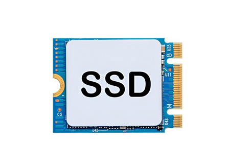
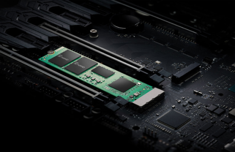
M2
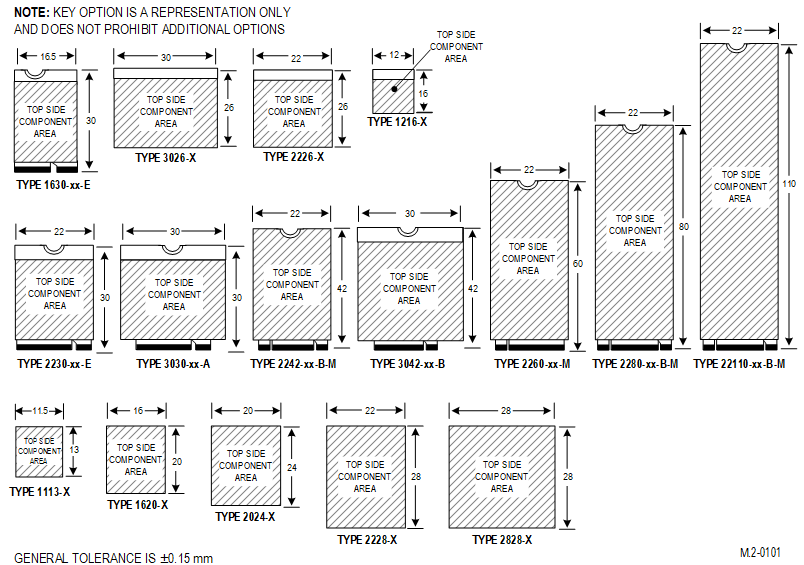
M.2 is a form factor specification for internally mounted SSDs. Formerly known as Next Generation Form Factor (NGFF), M.2 supports PCIe, SATA and USB interfaces and comes in various widths and lengths. It also has keying notches on the edge connector to designate various interface or PCIe lane configurations. M.2 is smaller than the typical 2.5” form factor SSD and is typically removable, except Type 1620 (BGA), which offers a ball grid array chip package and it typically mounted on the main system board.
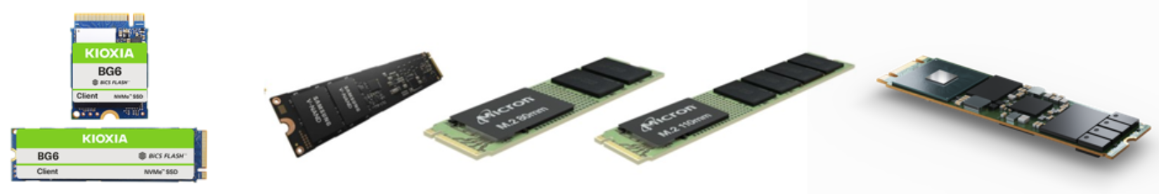
M.2 Illustrations left to right: courtesy of KIOXIA, courtesy of Samsung; courtesy of Micron; courtesy of Micron; courtesy of Solidigm
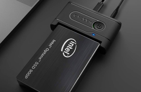
2.5-inch (U.2)
The 2.5-inch form factor is the most common deployment of an SSD, and is offered with PCIe (with NVMe), SAS or SATA interfaces. It is typically used in desktops, servers and storage systems built around hard disk drives (HDD). This form factor is commonly associated with the term U.2 and is sometimes referred to as the U.2 form factor. U.2 is defined as compliance with the PCI Express SFF-8639 Module specification, and no longer typically references SAS or SATA SSDs.
Mechanical/Electrical Specification
Connector Specification
Dimensions
Mechanical/Electrical Specification
Connector Specification
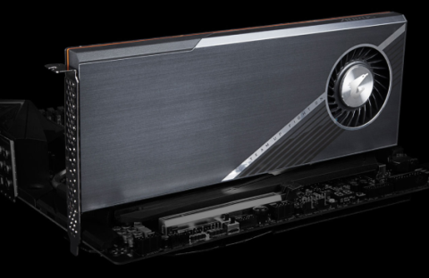
Add-In Card (AIC)
An Add-in Card (AIC) is a solid-state device that utilizes a standard card form factor such as a PCIe card. The AIC would usually use an interface such as PCIe, or possibly a mezzanine card of a standard form type. Given the larger physical size over an SSM, the AIC would typically have larger capacity and potentially higher performance. In addition, the larger size allows for the potential to add computational function to the storage device. Because of the versatility of the form factor, the AIC is a form factor that likely will constantly evolve for solid-state storage.
Actual SSC dimensions may be less, dependent on design.
PCIe cards can also come in multiple widths. Such a configuration allows mating with adjacent motherboard connectors, enabling increased performance by supporting more than 16 PCIe lanes.
Mechanical/Electrical Specification
Connector Specification