Sorry, you need to enable JavaScript to visit this website.

Join SNIA at Pure//Accelerate 2019: Austin, September 15-18

title of post

Equal parts education, information, and inspiration, Pure//Accelerate 2019 is where technology and innovation meet. It’s a place to learn about new products, solutions, and integrations. It is a place for technology enthusiasts to explore industry trends, network with like-minded companies, and map out how to stay ahead as the tech landscape rapidly changes.

SNIA Board Member and Chair of the Scalable Storage Management Technical Work Group Richelle Ahlvers will be joining SNIA Storage Management Initiative Board Member “Barkz” at Pure//Accelerate on Wednesday, September 18, 2019 from 2:00 p.m. – 2:45 p.m. for a presentation titled “Reel It In: SNIA Swordfish™ Scalable Storage Management

By extending the DMTF Redfish® API protocol and schema, SNIA Swordfish™ helps provide a unified approach for the management of storage equipment, data services, and servers. Learn how Pure Storage is using the Swordfish RESTful interface to support the implementation of fast, efficient storage products.

Take advantage of special pricing for SNIA members. Register here.

Olivia Rhye

Product Manager, SNIA

Find a similar article by tags

Leave a Reply

Comments

Name

Email Adress

Website

Save my name, email, and website in this browser for the next time I comment.

The Blurred Lines of Memory and Storage – A Q&A

John Kim

Jul 22, 2019

title of post
The lines are blurring as new memory technologies are challenging the way we build and use storage to meet application demands. That’s why the SNIA Networking Storage Forum (NSF) hosted a “Memory Pod” webcast is our series, “Everything You Wanted to Know about Storage, but were too Proud to Ask.” If you missed it, you can watch it on-demand here along with the presentation slides. We promised Q. Do tools exist to do secure data overwrite for security purposes? A. Most popular tools are cryptographic signing of the data where you can effectively erase the data by throwing away the keys. There are a number of technologies available; for example, the usual ones like BitLocker (part of Windows 10, for example) where the NVDIMM-P is tied to a specific motherboard. There are others where the data is encrypted as it is moved from NVDIMM DRAM to flash for the NVDIMM-N type. Other forms of persistent memory may offer their own solutions. SNIA is working on a security model for persistent memory, and there is a presentation on our work here. Q. Do you need to do any modification on OS or application to support Direct Access (DAX)? A. No, DAX is a feature of the OS (both Windows and Linux support it). DAX enables direct access to files stored in persistent memory or on a block device. Without DAX support in a file system, the page cache is generally used to buffer reads and writes to files, and DAX avoids that extra copy operation by performing reads and writes directly to the storage device. Q. What is the holdup on finalizing the NVDIMM-P standard? Timeline? A. The DDR5 NVDIMM-P standard is under development. Q. Do you have a webcast on persistent memory (PM) hardware too? A. Yes. The snia.org website has an educational library with over 2,000 educational assets. You can search for material on any storage-related topic. For instance, a search on persistent memory will get you all the presentations about persistent memory. Q. Must persistent memory have Data Loss Protection (DLP) A. Since it’s persistent, then the kind of DLP is the kind relevant for other classes of storage. This presentation on the SNIA Persistent Memory Security Threat Model covers some of this. Q. Traditional SSDs are subject to “long tail” latencies, especially as SSDs fill and writes must be preceded by erasures. Is this “long-tail” issue reduced or avoided in persistent memory? A. As PM is byte addressable and doesn’t require large block erasures, the flash kind of long tail latencies will be avoided. However, there are a number of proposed technologies for PM, and the read and write latencies and any possible long tail “stutters” will depend on their characteristics. Q. Does PM have any Write Amplification Factor (WAF) issues similar to SSDs? A. The write amplification (WA) associated with non-volatile memory (NVM) technologies comes from two sources.
  1. When the NVM material cannot be modified in place but requires some type of “erase before write” mechanism where the erasure domain (in bytes) is larger than the writes from the host to that domain.
  2. When the atomic unit of data placement on the NVM is larger than the size of incoming writes. Note the term used to denote this atomic unit can differ but is often referred to as a page or sector.
NVM technologies like the NAND used in SSDs suffer from both sources 1 and 2. This leads to very high write amplification under certain workloads, the worst being small random writes. It can also require over provisioning; that is, requiring more NVM internally than is exposed to the user externally. Persistent memory technologies (for example Intel’s 3DXpoint) only suffer from source 2 and can in theory suffer WA when the writes are small. The severity of the write amplification is dependent on how the memory controller interacts with the media. For example, current PM technologies are generally accessed over a DDR-4 channel by an x86 processor. x86 processors send 64 bytes at a time down to a memory controller, and can send more in certain cases (e.g. interleaving, multiple channel parallel writes, etc.). This makes it far more complex to account for WA than a simplistic random byte write model or in comparison with writing to a block device. Q. Persistent memory can provide faster access in comparison to NAND FLASH, but the cost is more for persistent memory. What do you think on the usability for this technology in future? A. Very good. See this presentation “MRAM, XPoint, ReRAM PM Fuel to Propel Tomorrow’s Computing Advances” by analysts, Tom Coughlin and Jim Handy for an in-depth treatment. Q. Does PM have a ‘lifespan’ similar to SSDs (e.g. 3 years with heavy writes, 5 years)? A. Yes, but that will vary by device technology and manufacturer. We expect the endurance to be very high; comparable or better than the best of flash technologies. Q. What is the performance difference between fast SSD vs “PM as DAX?” A. As you might expect us to say; it depends. PM via DAX is meant as a bridge to using PM natively, but you might expect to have improved performance from PM over NVMe as compared with a flash based SSD, as the latency of PM is much lower than flash; micro-seconds as opposed to low milliseconds. Q. Does DAX work the same as SSDs? A. No, but it is similar. DAX enables efficient block operations on PM similar to block operations on an SSD. Q. Do we have any security challenges with PME? A. Yes, and JEDEC is addressing them. Also see the Security Threat Model presentation here. Q. On the presentation slide of what is or is not persistent memory, are you saying that in order for something to be PM it must follow the SNIA persistent memory programming model? If it doesn’t follow that model, what is it? A. No, the model is a way of consuming this new technology. PM is anything that looks like memory (it is byte addressable via CPU load and store operations) and is persistent (it doesn’t require any external power source to retain information). Q. DRAM is basically a capacitor. Without power, the capacitor discharges and so the data is volatile. What exactly is persistent memory? Does it store data inside DRAM or it will use FLASH to store data? A. The presentation discusses two types of NVDIMM; one is based on DRAM and a flash backup that provides the persistence (that is NVDIMM-N), and the other is based on PM technologies (that is NVDIMM-P) that are themselves persistent, unlike DRAM. Q. Slide 15: If Persistent memory is fast and can appear as byte-addressable memory to applications, why bother with PM needing to be block addressed like disks? A. Because it’s going to be much easier to support applications from day one if PM can be consumed like very fast disks. Eventually, we expect PM to be consumed directly by applications, but that will require them to be upgraded to take advantage of it. Q. Can you please elaborate on byte and block addressable? A. Block addressable is the way we do I/O; that is, data is read and written in large blocks of data, typically 4Kbytes in size. Disk interfaces like SCSI or NVMe take commands to read and write these blocks of data to the external device by transferring the data to and from CPU memory, normally DRAM. Byte addressable means that we’re not doing any I/O at all; the CPU instructions for loading & storing fast registers from memory are used directly on PM. This removes an entire software stack to do the I/O, and means we can efficiently work on much smaller units of data; down to the byte as opposed to the fixed 4Kb demanded by I/O interfaces. You can learn more in our presentation “File vs. Block vs. Object Storage.” There are now 10 installments of the “Too Proud to Ask” webcast series, covering these topics: If you have an idea for an “Everything You Wanted to Know about Storage, but were too Proud to Ask” presentation, please let comment on this blog and the NSF team will put it up for consideration.

Olivia Rhye

Product Manager, SNIA

Find a similar article by tags

Leave a Reply

Comments

Name

Email Adress

Website

Save my name, email, and website in this browser for the next time I comment.

Your Questions Answered - Now You Can Be a Part of the Real World Workload Revolution!

Marty Foltyn

Jul 17, 2019

title of post

The SNIA Solid State Storage Initiative would like to thank everyone who attended our webcast: How To Be Part of the Real World Workload Revolution.  If you haven’t seen it yet, you can view the on demand version here.  You can find the slides here.

Eden Kim and Jim Fister led a discussion on the testmyworkload (TMW) tool and data repository, discussing how a collection of real-world workload data captures can revolutionize design and configuration of hardware, software and systems for the industry.   A new SNIA white paper available in both English and Chinese authored by Eden Kim, with an introduction by Tom Coughlin of Coughlin Associates and Jim Handy of Objective Analysis, discusses how we can all benefit by sharing traces of our digital workloads through the SNIA SSSI Real-World Workload Capture program.

In an environment where workloads are becoming more complex -- and the choices of hardware configuration for solid-state storage are growing -- the opportunity to better understand the characteristics of data transfers to and from the storage systems is critical.  By sharing real-world workloads on the Test My Workload repository, the industry can benefit overall in design and development at every level from SSD development to system configuration in the datacenter.

There were several questions asked in and after the webcast.  Here are some of the answers.  Any additional questions can be addressed to asksssi@snia.org.

Q: Shouldn't real world workloads have concurrent applications?  Also, wouldn’t any SQL workloads also log or journal sequential writes?

A: Yes.  Each capture shows all of the IO Streams that are being applied to each logical storage recognized by the OS.  These IO Streams are comprised of IOs generated by System activities as well as a variety of drivers, applications and OS activities.  The IOProfiler toolset allows you to not only see all of the IO Stream activity that occurs during a capture, but also allows you to parse, or filter, the capture to see just the IO Streams (and other metrics) that are of interest.

Q: Is there any collaboration with the SNIA IOTTA Technical Work Group on workload or trace uploading?

A:  While IOTTA TWG and SSS TWG work closely together, an IO Capture is fundamentally different from an IO Trace and hence is not able to be presented on the IOTTA trace repository.  An IO Trace collects all of the data streams that occur during the IO Trace capture period and results in a very large file.  An IO Capture, on the other hand, captures statistics on the observed IO Streams and saves these statistics to a table.  Hence, no actual personal or user data is captured in an IO Capture, only the statistics on the IO Streams. Because IO Captures are a series of record tables for individual time steps, the format is not compatible with a repository for the streaming data captured in an IO Trace.

For example, an IO Trace could do a capture where 50,000 RND 4K Write and 50,000 RND 4K Read IOPS are recorded, resulting in 100,000 4K transfers, or 40M bytes of data.  OTOH, an IO Capture that collects statistics would log the fact that 50,000 RND 4K Writes and 50,000 RND 4K Reads occurred… a simple two item entry in a table.  Of course, the IOPS, Response Times, Queue Depths and LBA Ranges could also be tracked resulting in a table of 100,000 entries times the above 4 metrics, but 400,000 table entries is much smaller than 40 MB of data.

Both of these activities are useful, and the SNIA supports both.

Q: Can the traces capture a cluster workload or just single server?

A: IO Captures capture the IO Streams that are observed going from User space to all logical storage recognized by the OS.  Accordingly, for clusters, there will be an individual capture for each logical unit.  Note that all logical device captures can be aggregated into a single capture for analysis with the advanced analytics offered by the commercial IOProfiler tools.

Q: Have you seen situation where the IO size on the wire does not matched what application request?  Example Application request 256K but driver chopped the IO into multiple 16K before sent to the storage. How would we verify this type of issue?

A: Yes, this is a common situation. Applications may generate a large block SEQ IO Stream for video on demand.  However, that large block SEQ IO Stream is often fragmented into concurrent RND block sizes.  For example, in Linux OS, a 1MB file is often fragmented into random concurrent 128K block sizes for transmission to and from storage, but then coalesced back into a single 1024K BS in user space..

Q: Will you be sharing the costs for your tools or systems?

A: The tool demonstrated in the webcast is available free at testmyworkload.com (TMW).  This is done to build the repository of workloads at the TMW site.  Calypso Systems does have a set of Pro tools built around the TMW application.  Contact Calypso for specific details.

Q: Can the capture be replayed on different drives?

A: Yes.  In fact, this is one of the reasons that the tool was created.  The tool and repository of workloads are intended to be used as a way to compare drive and system performance, as well as tune software for real-world conditions.

Q: How are you tracking compressibility & duplication if the user does not turn on compression or dedupe?

A: The user must turn on compression or duplication at the beginning of the capture to see these metrics.

Q: An end user can readily use this to see what their real world workload looks like.  But, how could an SSD vendor mimic the real world workload or get a more "realworld-like" workload for use in common benchmarking tools like FIO & Sysbench?

A: The benchmarking tools mentioned are synthetic workloads, and write a predictable stream to and from the drive.  IO Captures ideally are run as a replay test that recreates the sequence of changing IO Stream combinations and Queue Depths observed during the capture.  While the Calypso toolset can do this automatically, free benchmark tools like FIO and sysbench may not be able to change QDs and IO Stream combinations from step to step in a test script.  However, the IO Capture will also provide a cumulative workload that list the dominant IO Streams and their percentage of occurrence.  This list of dominant IO Streams can be used with fio or sysbench to create a synthetic composite IO stream workload.

Q: Is it possible to use the tool to track CPU State such as IOWAIT or AWAIT based on the various streams?

A: Yes, IO Captures contain statistics on CPU usage such as CPU System Usage %, CPU IO Wait, CPU User usage, etc.

Q: Can we get more explanation of demand intensity and comparison to queue depth?

A: Demand Intensity (DI) is used to refer to the outstanding IOs at a given level of the software/hardware stack.  It may be referred to simply as the outstanding Queue Depth (QD) or as the number of outstanding Thread Count (TC) and QD.  The relevance of TC depends on where in the stack you are measuring the DI.  User QD varies from level to level and depends on what each layer of abstraction is doing.  Usually, focus is paid to the IO Scheduler and the total outstanding IOs at the block IO level.  Regardless of nomenclature, it is important to understand the DI as your workload traverses the IO Stack and to be able to minimize bottlenecks due to high DI.

Q: In these RWSW application traces do these include non-media command percentages such as identify and read log page (SMART), sleep states, etc.?  Depending on the storage interface and firmware this can adversely affect performance/QoS.

A: IO Capture metrics are the IO Streams at the logical storage level and thus do not include protocol level commands.  Non performance IO commands such as TRIMs can be recorded, and SMART logs can be tracked if access to the physical storage is provided.

Q: Isn't latency a key performance metric for these workloads so collecting only 2 minute burst might not show latency anomalies?

A: IO Captures average the statistics over a selected time window.  Each individual IO Stream and its metrics are recorded and tabulated on a table but the time window average is what is displayed on the IO Stream map.  Of course, the min and max Response times over the 2 minute window are displayed, but the individual IO latencies are not displayed.  In order to track IO Bursts, the time window resolution should be set to a narrow time range, such as 100 mS or less, in order to distinguish IO Bursts and Host Idle times.

Olivia Rhye

Product Manager, SNIA

Find a similar article by tags

Leave a Reply

Comments

Name

Email Adress

Website

Save my name, email, and website in this browser for the next time I comment.

Your Questions Answered – Now You Can Be a Part of the Real World Workload Revolution!

Marty Foltyn

Jul 17, 2019

title of post
The SNIA Solid State Storage Initiative would like to thank everyone who attended our webcast: How To Be Part of the Real World Workload Revolution.  If you haven’t seen it yet, you can view the on demand version here.  You can find the slides here. Eden Kim and Jim Fister led a discussion on the testmyworkload (TMW) tool and data repository, discussing how a collection of real-world workload data captures can revolutionize design and configuration of hardware, software and systems for the industry.   A new SNIA white paper available in both English and Chinese authored by Eden Kim, with an introduction by Tom Coughlin of Coughlin Associates and Jim Handy of Objective Analysis, discusses how we can all benefit by sharing traces of our digital workloads through the SNIA SSSI Real-World Workload Capture program. In an environment where workloads are becoming more complex — and the choices of hardware configuration for solid-state storage are growing — the opportunity to better understand the characteristics of data transfers to and from the storage systems is critical.  By sharing real-world workloads on the Test My Workload repository, the industry can benefit overall in design and development at every level from SSD development to system configuration in the datacenter. There were several questions asked in and after the webcast.  Here are some of the answers.  Any additional questions can be addressed to asksssi@snia.org. Q: Shouldn’t real world workloads have concurrent applications?  Also, wouldn’t any SQL workloads also log or journal sequential writes? A: Yes.  Each capture shows all of the IO Streams that are being applied to each logical storage recognized by the OS.  These IO Streams are comprised of IOs generated by System activities as well as a variety of drivers, applications and OS activities.  The IOProfiler toolset allows you to not only see all of the IO Stream activity that occurs during a capture, but also allows you to parse, or filter, the capture to see just the IO Streams (and other metrics) that are of interest. Q: Is there any collaboration with the SNIA IOTTA Technical Work Group on workload or trace uploading? A:  While IOTTA TWG and SSS TWG work closely together, an IO Capture is fundamentally different from an IO Trace and hence is not able to be presented on the IOTTA trace repository.  An IO Trace collects all of the data streams that occur during the IO Trace capture period and results in a very large file.  An IO Capture, on the other hand, captures statistics on the observed IO Streams and saves these statistics to a table.  Hence, no actual personal or user data is captured in an IO Capture, only the statistics on the IO Streams. Because IO Captures are a series of record tables for individual time steps, the format is not compatible with a repository for the streaming data captured in an IO Trace. For example, an IO Trace could do a capture where 50,000 RND 4K Write and 50,000 RND 4K Read IOPS are recorded, resulting in 100,000 4K transfers, or 40M bytes of data.  OTOH, an IO Capture that collects statistics would log the fact that 50,000 RND 4K Writes and 50,000 RND 4K Reads occurred… a simple two item entry in a table.  Of course, the IOPS, Response Times, Queue Depths and LBA Ranges could also be tracked resulting in a table of 100,000 entries times the above 4 metrics, but 400,000 table entries is much smaller than 40 MB of data. Both of these activities are useful, and the SNIA supports both. Q: Can the traces capture a cluster workload or just single server? A: IO Captures capture the IO Streams that are observed going from User space to all logical storage recognized by the OS.  Accordingly, for clusters, there will be an individual capture for each logical unit.  Note that all logical device captures can be aggregated into a single capture for analysis with the advanced analytics offered by the commercial IOProfiler tools. Q: Have you seen situation where the IO size on the wire does not matched what application request?  Example Application request 256K but driver chopped the IO into multiple 16K before sent to the storage. How would we verify this type of issue? A: Yes, this is a common situation. Applications may generate a large block SEQ IO Stream for video on demand.  However, that large block SEQ IO Stream is often fragmented into concurrent RND block sizes.  For example, in Linux OS, a 1MB file is often fragmented into random concurrent 128K block sizes for transmission to and from storage, but then coalesced back into a single 1024K BS in user space.. Q: Will you be sharing the costs for your tools or systems? A: The tool demonstrated in the webcast is available free at testmyworkload.com (TMW).  This is done to build the repository of workloads at the TMW site.  Calypso Systems does have a set of Pro tools built around the TMW application.  Contact Calypso for specific details. Q: Can the capture be replayed on different drives? A: Yes.  In fact, this is one of the reasons that the tool was created.  The tool and repository of workloads are intended to be used as a way to compare drive and system performance, as well as tune software for real-world conditions. Q: How are you tracking compressibility & duplication if the user does not turn on compression or dedupe? A: The user must turn on compression or duplication at the beginning of the capture to see these metrics. Q: An end user can readily use this to see what their real world workload looks like.  But, how could an SSD vendor mimic the real world workload or get a more “realworld-like” workload for use in common benchmarking tools like FIO & Sysbench? A: The benchmarking tools mentioned are synthetic workloads, and write a predictable stream to and from the drive.  IO Captures ideally are run as a replay test that recreates the sequence of changing IO Stream combinations and Queue Depths observed during the capture.  While the Calypso toolset can do this automatically, free benchmark tools like FIO and sysbench may not be able to change QDs and IO Stream combinations from step to step in a test script.  However, the IO Capture will also provide a cumulative workload that list the dominant IO Streams and their percentage of occurrence.  This list of dominant IO Streams can be used with fio or sysbench to create a synthetic composite IO stream workload. Q: Is it possible to use the tool to track CPU State such as IOWAIT or AWAIT based on the various streams? A: Yes, IO Captures contain statistics on CPU usage such as CPU System Usage %, CPU IO Wait, CPU User usage, etc. Q: Can we get more explanation of demand intensity and comparison to queue depth? A: Demand Intensity (DI) is used to refer to the outstanding IOs at a given level of the software/hardware stack.  It may be referred to simply as the outstanding Queue Depth (QD) or as the number of outstanding Thread Count (TC) and QD.  The relevance of TC depends on where in the stack you are measuring the DI.  User QD varies from level to level and depends on what each layer of abstraction is doing.  Usually, focus is paid to the IO Scheduler and the total outstanding IOs at the block IO level.  Regardless of nomenclature, it is important to understand the DI as your workload traverses the IO Stack and to be able to minimize bottlenecks due to high DI. Q: In these RWSW application traces do these include non-media command percentages such as identify and read log page (SMART), sleep states, etc.?  Depending on the storage interface and firmware this can adversely affect performance/QoS. A: IO Capture metrics are the IO Streams at the logical storage level and thus do not include protocol level commands.  Non performance IO commands such as TRIMs can be recorded, and SMART logs can be tracked if access to the physical storage is provided. Q: Isn’t latency a key performance metric for these workloads so collecting only 2 minute burst might not show latency anomalies? A: IO Captures average the statistics over a selected time window.  Each individual IO Stream and its metrics are recorded and tabulated on a table but the time window average is what is displayed on the IO Stream map.  Of course, the min and max Response times over the 2 minute window are displayed, but the individual IO latencies are not displayed.  In order to track IO Bursts, the time window resolution should be set to a narrow time range, such as 100 mS or less, in order to distinguish IO Bursts and Host Idle times.

Olivia Rhye

Product Manager, SNIA

Find a similar article by tags

Leave a Reply

Comments

Name

Email Adress

Website

Save my name, email, and website in this browser for the next time I comment.

SNIA’s Self-contained Information Retention Format (SIRF) v1.0 Published as an ISO Standard

title of post
[caption id="attachment_1934" align="alignright" width="150"] Simona Rabinovici-Cohen
IBM Research - Haifa[/caption] The SNIA standard for a logical container format called the Self-contained Information Retention Format (SIRF) v1.0 has now been published as an ISO standard thanks to the diligence and hard work of SNIA’s Long Term Retention Technical Work Group (LTR TWG).This new ISO standard (ISO/IEC 23681:2019) enables long-term hard disk, cloud, and tape-based containers a way to effectively and efficiently preserve and secure digital information for many decades, even with the ever-changing technology landscape. The demand for digital data preservation has increased in recent years. Maintaining a large amount of data for long periods of time (months, years, decades, or even forever) becomes even more important given government regulations such as HIPAA, Sarbanes-Oxley, OSHA, and many others that define specific preservation periods for critical records. The SIRF standard addresses the technical challenges of long-term digital information retention & preservation for both physical and logical preservation. It is a storage container of digital preservation objects that provides a catalog with metadata related to the entire contents of the container, individual objects, and their relationships. This standardized metadata help interpret the preservation objects in the future. Key value to the industry:
  • Serialization for the cloud is supported using OpenStack Swift object storage as an example, and SIRF serialization for tapes is supported using the LTFS ISO standard
  • Serialization for adapted industry technologies is provided in the specification
  • Plays a key role in the preservation and retention of critical data, and because it is interpretable by future data preservation systems, it has the benefit of greatly reducing the associated costs of digital preservation
For more information, please visit https://www.snia.org/ltr. With the publication of the ISO standard, the work of the LTR TWG has been completed.  We would like to thank the TWG contributors and SNIA management for making this accomplishment happen.

Olivia Rhye

Product Manager, SNIA

Find a similar article by tags

Leave a Reply

Comments

Name

Email Adress

Website

Save my name, email, and website in this browser for the next time I comment.

SNIA at Flash Memory Summit 2019 - Your Guide Here!

Marty Foltyn

Jul 8, 2019

title of post

SNIA technical work and education advances will play a prominent role in the program at the 2019 Flash Memory Summit, August 5-8, 2019, in Santa Clara, CA.  Over 40 speakers will present on key standards activities and education initiatives, including the first ever FMS Persistent Memory Hackathon hosted by SNIA.  Check out your favorite technology (or all), and learn what SNIA is doing in these sessions:

SNIA-At-A-Glance

  • •SNIA Solid State Storage Reception
    Monday, August 5, 5:30 pm, Room 209/210
  • •SNIA Standards mainstage presentation by Michael Oros, SNIA Executive Director
    Tuesday, August 6, 2:50 pm, Mission City Ballroom
  • •Beer and Pizza with SNIA Experts on Persistent Memory/NVDIMM, Remote Persistent Memory/Open Fabrics, SNIA Swordfish, and more
    Tuesday, August 6, 7:15 pm – 9:00 pm, Ballrooms A-C
  • •SNIA Solid State Storage Initiative booth #820 featuring Persistent Memory demos and Performance, Computational Storage, and SNIA Swordfish discussions
    Tuesday, August 6, 4:00 pm – 7:00 pm; Wednesday August 7, Noon to 7 pm; and Thursday, August 8, 10:00 am – 2:30 pm, Exhibit Hall

Persistent Memory

  • SNIA Persistent Memory Programming Tutorial and Introduction to the FMS Persistent Memory Hackathon hosted by SNIA
    Learn how programming persistent memory works and get started on your own “hacks”
    Monday, August 5, 1:00 p.m. – 5:00 p.m, Room 209/210

  • •Persistent Memory Hackathon hosted by SNIA
    Bring your laptop and drop by anytime over the two days. SNIA persistent memory experts will support software developers in a live coding exercise to better understand the various tiers and modes of persistent memory and explore existing best practices.
    Tuesday, August 6 and Wednesday August 7, 8:30 am – 7:00 pm, Great America Ballroom Foyer
  • •Persistent Memory Track sessions sponsored by SNIA, JEDEC, and Open Fabrics Alliance
    See experts speak on Advances in Persistent Memory and PM Software and Applications in sessions PMEM-101-1 and PMEM-102-1
    Tuesday, August 6, 8:30 am – 10:50 am in Ballroom E and 3:40 pm – 6:00 pm, in Great America Ballroom J
  • •Persistent Memory Track sessions sponsored by SNIA, JEDEC, and Open Fabrics Alliance
    The track continues with sessions on Remote Persistent Memory and the latest research in the field in sessions PMEM-201-1 and PMEM-202-1
    Wednesday, August 7, 8:30 am – 10:50 am and 3:20 pm – 5:45 pm, Great America Meeting Room 3

Computational Storage

  • •Don’t miss the first ever Computational Storage track at FMS. This SNIA sponsored day features expert presentations and panels on Controllers and Technology, Deploying Solutions, Implementation Methods and Applications.(COMP-301A-1; COMP-301B-1; COMP-302A-1; COMP-302B-1)
    Thursday, August 8, 8:30 am – 10:50 am and 3:20 pm – 5:45 pm, in Ballroom A

Form Factors

  • •Learn what the SFF TA Technical Work Group has been doing in the session New Enterprise and Data Center SSD Form Factors (SSDS-201B-1)
    Wednesday, August 7, 9:45 am -10:50 am, in Great America Ballroom K

SNIA Swordfish

  • •Hear an update on Storage Management with Swordfish APIs for Open-Channel SSDs in session SOFT-201-1
    Wednesday, August 7, 9:45 am -10:50 am, in Ballroom F

Object Drives

  • •Learn about Standardization for a Key Value Interface Underway at NVM Express and SNIA in session NVME-201-1
    Wednesday, August 7,8:30 am – 9:35 am, in Great America Meeting Room 2

Olivia Rhye

Product Manager, SNIA

Find a similar article by tags

Leave a Reply

Comments

Name

Email Adress

Website

Save my name, email, and website in this browser for the next time I comment.

SNIA at Flash Memory Summit 2019 – Your Guide Here!

Marty Foltyn

Jul 8, 2019

title of post
SNIA technical work and education advances will play a prominent role in the program at the 2019 Flash Memory Summit, August 5-8, 2019, in Santa Clara, CA.  Over 40 speakers will present on key standards activities and education initiatives, including the first ever FMS Persistent Memory Hackathon hosted by SNIA.  Check out your favorite technology (or all), and learn what SNIA is doing in these sessions: SNIA-At-A-Glance
  • •SNIA Solid State Storage Reception Monday, August 5, 5:30 pm, Room 209/210
  • •SNIA Standards mainstage presentation by Michael Oros, SNIA Executive Director Tuesday, August 6, 2:50 pm, Mission City Ballroom
  • •Beer and Pizza with SNIA Experts on Persistent Memory/NVDIMM, Remote Persistent Memory/Open Fabrics, SNIA Swordfish, and more Tuesday, August 6, 7:15 pm – 9:00 pm, Ballrooms A-C
  • •SNIA Solid State Storage Initiative booth #820 featuring Persistent Memory demos and Performance, Computational Storage, and SNIA Swordfish discussions Tuesday, August 6, 4:00 pm – 7:00 pm; Wednesday August 7, Noon to 7 pm; and Thursday, August 8, 10:00 am – 2:30 pm, Exhibit Hall
Persistent Memory
  • SNIA Persistent Memory Programming Tutorial and Introduction to the FMS Persistent Memory Hackathon hosted by SNIA Learn how programming persistent memory works and get started on your own “hacks” Monday, August 5, 1:00 p.m. – 5:00 p.m, Room 209/210
  • Persistent Memory Hackathon hosted by SNIA Bring your laptop and drop by anytime over the two days. SNIA persistent memory experts will support software developers in a live coding exercise to better understand the various tiers and modes of persistent memory and explore existing best practices. Tuesday, August 6 and Wednesday August 7, 8:30 am – 7:00 pm, Great America Ballroom Foyer
  • Persistent Memory Track sessions sponsored by SNIA, JEDEC, and OpenFabrics Alliance See experts speak on Advances in Persistent Memory and PM Software and Applications in sessions PMEM-101-1 and PMEM-102-1 Tuesday, August 6, 8:30 am – 10:50 am in  Ballroom E and 3:40 pm – 6:00 pm in Great America Ballroom J
  • Persistent Memory Track sessions sponsored by SNIA, JEDEC, and OpenFabrics Alliance The track continues with sessions on Remote Persistent Memory and the latest research in the field in sessions PMEM-201-1 and PMEM-202-1 Wednesday, August 7, 8:30 am – 10:50 am and 3:20 pm – 5:45 pm in Great America Meeting Room 3
Computational Storage
  • •Don’t miss the first ever Computational Storage track at FMS. This SNIA sponsored day features expert presentations and panels on Controllers and Technology, Deploying Solutions, Implementation Methods and Applications.(COMP-301A-1; COMP-301B-1; COMP-302A-1; COMP-302B-1) Thursday, August 8, 8:30 am – 10:50 am and 3:20 pm – 5:45 pm, in Ballroom A
Form Factors
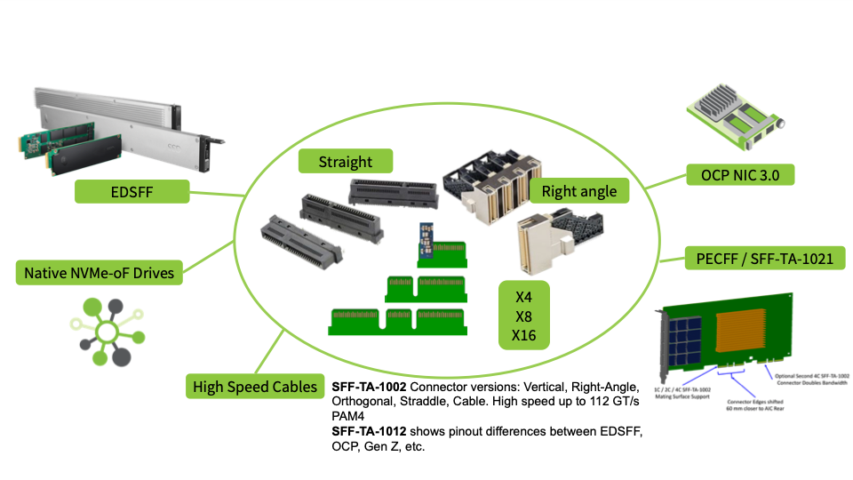
  • •Learn what the SFF TA Technical Work Group has been doing in the session New Enterprise and Data Center SSD Form Factors (SSDS-201B-1) Wednesday, August 7, 9:45 am -10:50 am, in Great America Ballroom K
SNIA Swordfish
  • •Hear an update on Storage Management with Swordfish APIs for Open-Channel SSDs in session SOFT-201-1 Wednesday, August 7, 9:45 am -10:50 am, in Ballroom F
Object Drives
  • •Learn about Standardization for a Key Value Interface Underway at NVM Express and SNIA in session NVME-201-1 Wednesday, August 7,8:30 am – 9:35 am, in Great America Meeting Room 2

Olivia Rhye

Product Manager, SNIA

Find a similar article by tags

Leave a Reply

Comments

Name

Email Adress

Website

Save my name, email, and website in this browser for the next time I comment.

Storage Congestion on the Network Q&A

Tim Lustig

Jul 1, 2019

title of post
As more storage traffic traverses the network, the risk of congestion leading to higher-than-expected latencies and lower-than expected throughput has become common. That's why the SNIA Networking Storage Forum (NSF) hosted a live webcast earlier this month, Introduction to Incast, Head of Line Blocking, and Congestion Management. In this webcast (which is now available on-demand), our SNIA experts discussed how Ethernet, Fibre Channel and InfiniBand each handles increased traffic. The audience at the live event asked some great questions, as promised, here are answers to them all. Q. How many IP switch vendors today support Data Center TCP (DCTCP)? A. In order to maintain vendor neutrality, we won't get into the details. But several IP switch vendors do support DCTCP. Note that many Ethernet switches support basic explicit congestion notification (ECN), but DCTCP requires a more detailed version of ECN marking on the switch and also requires that at least some of the endpoints (servers and storage) support DCTCP. Q. One point I missed around ECN/DCTCP was that the configuration for DCTCP on the switches is virtually identical to what you need to set for DCQCN (RoCE) - but you'd still want two separate queues between DCTCP and RoCE since they don't really play along well. A. Yes, RoCE congestion control also takes advantage of ECN and has some similarities to DCTCP. Using different priorities for DCTCP. If using Priority Flow Control (PFC), where RoCE is being kept in a no-drop traffic class, you will want to ensure that RoCE storage traffic and TCP-based storage traffic are in separate priorities. If you are not using lossless transport for RoCE, however, using different priorities for DCTCP and RoCE traffic is recommended, but not required. Q. Is over-subscription a case of the server and/or switch/endpoint being faster than the link? A. Over-subscription is not usually caused when one server is faster than one link; in that case the fast server's throughput is simply limited to the link speed (like a 32G FC HBA plugged into a 16G FC switch port). But over-subscription can be caused when multiple nodes write or read more data than one switch port, switch, or switch uplink can handle. For example if six 8G Fibre Channel nodes are connected to one 16G FC switch port, that port is 3X oversubscribed. Or if sixteen 16G FC servers connect to a switch and all of them simultaneously try to send or receive traffic to the rest of the network through two 64G FC switch uplinks, then those switch uplinks are 2X oversubscribed (16x16G is two times the bandwidth of 2x64G). Similar oversubscription scenarios can be created with Ethernet and InfiniBand. Oversubscription is not always bad especially if the "downstream" links are not all expected to be handling data at full line rate all of the time. Q. Can't the switch regulate the incoming flow? A. Yes if you have flow control or a lossless network then each switch can pause incoming traffic on any port if its buffers are getting too full. However, if the switch pauses incoming traffic for too long in a lossless network, this can cause congestion to spread to nearby switches. In a lossy network, the switch could also selectively drop packets to signal congestion to the senders. While the lossless mechanism allows the switch to regulate the incoming flow and deal with congestion, it does not avoid congestion. To avoid too much traffic being generated in the first place, the traffic sources (server or storage) need to throttle the transmission rate. The aggregate traffic generated across all sources to one destination needs to be lower than the link speed of the destination port to prevent oversubscription. The FC standards committee is working on exactly such a proposal. See answer to question below. Q. Is the FC protocol considering a back-off mechanism like DCTCP? A. The Fibre Channel standards organization T11 recently began investigating methods for providing notifications from the Fabric to the end devices to address issues associated with link integrity, congestion, and discarded frames. This effort began in December 2018 and is expected to be complete in 2019. Q. Do long distance FC networks need to have giant buffers to handle all the data required to keep the link full for the time that it takes to release credit? If not, how is the long-distance capability supported at line speed, given the time delay to return credit? A. As the link comes up, the transmitter is initialized credits equal to the number of buffers available in the receiver. This preloaded credits for the transmitter has to be sufficiently high to allow for the time it takes for credits to come back from receiver. Longer delay in credit return requires higher number of buffers/credits to maintain maximum performance on the link. In general, the credit delay increases with link distance because of the increased propagation delay for the frame from transmitter to receiver and for the credit from receiver to transmitter. So, yes you do need more buffers for longer distance. This is true with any lossless network - Fibre Channel, InfiniBand and lossless Ethernet. Q. Shouldn't storage systems have the same credit-based system to regulate the incoming flow to the switch from the storage systems? A. Yes, in a credit-based lossless network (Fibre Channel or InfiniBand) every port, including the port on the storage system, is required to implement the credit-based system to maintain the lossless characteristics. This allows the switch to control how much traffic is sent by the storage system to switch. Q. Is the credit issuance from the switch or from the tx device? A. The credit mechanism works in both ways on a link, bidirectionally. So if a server is exchanging data with a switch, the switch uses credits to regulate traffic coming from the server and the server uses credits to regulate traffic coming from the switch. This mechanism is the same on every Fibre Channel link be it Server-to-Switch, Switch-to-Switch or Switch-to-Server. Q. Can you comment on DCTCP (datacenter TCP), and the current work @IETF (L4S - low loss, low latency, scalable transport)? A. There are several possible means by which congestion can be observed and quite a few ways of managing that congestion. ECN and DCTCP were selected for the simple reason that they are established technologies (even if not widely known), and have been completed. As the commenter notes, however, there are other means by which congestion is being handled. One of these is L4S, which is currently (as of this writing) a work in progress in the IETF. Learn more here. Q. Virtual Lanes / Virtual Channel would be equivalent to Priority Flow control - the trick is, that in standard TCP/IP, no one really uses different queues/ PCP / QoS to really differentiate between flows of the same application but different sessions, only different applications (VoIP, Data, Storage, ...) A. This is not quite correct. PFC has to do with an application of flow control upon a priority; it's not the same thing as a priority/virtual lane/virtual channel itself. The commenter is correct, however, that most people do not see a need for isolating out storage applications on their TCP priorities, but then they wonder why they're not getting stellar performance. Q. Can every ECN capable switch be configured to support DCTCP? A. Switches are, by their nature, stateless. That means that there is no need for a switch to be 'configured' for DCTCP, regardless of whether or not ECN is being used. So, in the strictest sense, any switch that is capable of ECN is already "configured" for DCTCP. Q. Is it true that admission control (FC buffer credit scheme) has the drawback of usually underutilization of the links...especially if your workload uses many small frames, rather than full-sized frames? A. This is correct in certain circumstances. Early in the presentation we discussed how it's important to plan for the  application, not the protocol (see slide #9).  As noted in the presentation, "the application is King."
Part of the process of architecting good FC design is to ensure that the proper oversubscription ratios are used (i.e., oversubscription involves the amount of host devices that are allowed to connect to each storage device). These oversubscription ratios are identified by the applications that have specific requirements, such as databases, etc. If a deterministic network like Fibre Channel is not architected with this in mind, it will indeed seem like a drawback.
       

Olivia Rhye

Product Manager, SNIA

Find a similar article by tags

Leave a Reply

Comments

Name

Email Adress

Website

Save my name, email, and website in this browser for the next time I comment.

Storage Congestion on the Network Q&A

Tim Lustig

Jul 1, 2019

title of post
As more storage traffic traverses the network, the risk of congestion leading to higher-than-expected latencies and lower-than expected throughput has become common. That’s why the SNIA Networking Storage Forum (NSF) hosted a live webcast earlier this month, Introduction to Incast, Head of Line Blocking, and Congestion Management. In this webcast (which is now available on-demand), our SNIA experts discussed how Ethernet, Fibre Channel and InfiniBand each handles increased traffic. The audience at the live event asked some great questions, as promised, here are answers to them all. Q. How many IP switch vendors today support Data Center TCP (DCTCP)? A. In order to maintain vendor neutrality, we won’t get into the details. But several IP switch vendors do support DCTCP. Note that many Ethernet switches support basic explicit congestion notification (ECN), but DCTCP requires a more detailed version of ECN marking on the switch and also requires that at least some of the endpoints (servers and storage) support DCTCP. Q. One point I missed around ECN/DCTCP was that the configuration for DCTCP on the switches is virtually identical to what you need to set for DCQCN (RoCE) – but you’d still want two separate queues between DCTCP and RoCE since they don’t really play along well. A. Yes, RoCE congestion control also takes advantage of ECN and has some similarities to DCTCP. Using different priorities for DCTCP. If using Priority Flow Control (PFC), where RoCE is being kept in a no-drop traffic class, you will want to ensure that RoCE storage traffic and TCP-based storage traffic are in separate priorities. If you are not using lossless transport for RoCE, however, using different priorities for DCTCP and RoCE traffic is recommended, but not required. Q. Is over-subscription a case of the server and/or switch/endpoint being faster than the link? A. Over-subscription is not usually caused when one server is faster than one link; in that case the fast server’s throughput is simply limited to the link speed (like a 32G FC HBA plugged into a 16G FC switch port). But over-subscription can be caused when multiple nodes write or read more data than one switch port, switch, or switch uplink can handle. For example if six 8G Fibre Channel nodes are connected to one 16G FC switch port, that port is 3X oversubscribed. Or if sixteen 16G FC servers connect to a switch and all of them simultaneously try to send or receive traffic to the rest of the network through two 64G FC switch uplinks, then those switch uplinks are 2X oversubscribed (16x16G is two times the bandwidth of 2x64G). Similar oversubscription scenarios can be created with Ethernet and InfiniBand. Oversubscription is not always bad especially if the “downstream” links are not all expected to be handling data at full line rate all of the time. Q. Can’t the switch regulate the incoming flow? A. Yes if you have flow control or a lossless network then each switch can pause incoming traffic on any port if its buffers are getting too full. However, if the switch pauses incoming traffic for too long in a lossless network, this can cause congestion to spread to nearby switches. In a lossy network, the switch could also selectively drop packets to signal congestion to the senders. While the lossless mechanism allows the switch to regulate the incoming flow and deal with congestion, it does not avoid congestion. To avoid too much traffic being generated in the first place, the traffic sources (server or storage) need to throttle the transmission rate. The aggregate traffic generated across all sources to one destination needs to be lower than the link speed of the destination port to prevent oversubscription. The FC standards committee is working on exactly such a proposal. See answer to question below. Q. Is the FC protocol considering a back-off mechanism like DCTCP? A. The Fibre Channel standards organization T11 recently began investigating methods for providing notifications from the Fabric to the end devices to address issues associated with link integrity, congestion, and discarded frames. This effort began in December 2018 and is expected to be complete in 2019. Q. Do long distance FC networks need to have giant buffers to handle all the data required to keep the link full for the time that it takes to release credit? If not, how is the long-distance capability supported at line speed, given the time delay to return credit? A. As the link comes up, the transmitter is initialized credits equal to the number of buffers available in the receiver. This preloaded credits for the transmitter has to be sufficiently high to allow for the time it takes for credits to come back from receiver. Longer delay in credit return requires higher number of buffers/credits to maintain maximum performance on the link. In general, the credit delay increases with link distance because of the increased propagation delay for the frame from transmitter to receiver and for the credit from receiver to transmitter. So, yes you do need more buffers for longer distance. This is true with any lossless network – Fibre Channel, InfiniBand and lossless Ethernet. Q. Shouldn’t storage systems have the same credit-based system to regulate the incoming flow to the switch from the storage systems? A. Yes, in a credit-based lossless network (Fibre Channel or InfiniBand) every port, including the port on the storage system, is required to implement the credit-based system to maintain the lossless characteristics. This allows the switch to control how much traffic is sent by the storage system to switch. Q. Is the credit issuance from the switch or from the tx device? A. The credit mechanism works in both ways on a link, bidirectionally. So if a server is exchanging data with a switch, the switch uses credits to regulate traffic coming from the server and the server uses credits to regulate traffic coming from the switch. This mechanism is the same on every Fibre Channel link be it Server-to-Switch, Switch-to-Switch or Switch-to-Server. Q. Can you comment on DCTCP (datacenter TCP), and the current work @IETF (L4S – low loss, low latency, scalable transport)? A. There are several possible means by which congestion can be observed and quite a few ways of managing that congestion. ECN and DCTCP were selected for the simple reason that they are established technologies (even if not widely known), and have been completed. As the commenter notes, however, there are other means by which congestion is being handled. One of these is L4S, which is currently (as of this writing) a work in progress in the IETF. Learn more here. Q. Virtual Lanes / Virtual Channel would be equivalent to Priority Flow control – the trick is, that in standard TCP/IP, no one really uses different queues/ PCP / QoS to really differentiate between flows of the same application but different sessions, only different applications (VoIP, Data, Storage, …) A. This is not quite correct. PFC has to do with an application of flow control upon a priority; it’s not the same thing as a priority/virtual lane/virtual channel itself. The commenter is correct, however, that most people do not see a need for isolating out storage applications on their TCP priorities, but then they wonder why they’re not getting stellar performance. Q. Can every ECN capable switch be configured to support DCTCP? A. Switches are, by their nature, stateless. That means that there is no need for a switch to be ‘configured’ for DCTCP, regardless of whether or not ECN is being used. So, in the strictest sense, any switch that is capable of ECN is already “configured” for DCTCP. Q. Is it true that admission control (FC buffer credit scheme) has the drawback of usually underutilization of the links…especially if your workload uses many small frames, rather than full-sized frames? A. This is correct in certain circumstances. Early in the presentation we discussed how it’s important to plan for the application, not the protocol (see slide #9 from the presentation). As noted in the presentation, “the application is King.” Part of the process of architecting good FC design is to ensure that the proper oversubscription ratios are used (oversubscription involves the amount of host devices that are allowed to connect to each storage device). These oversubscription ratios are identified by the applications that have specific requirements, such as databases, etc. If a deterministic network like Fibre Channel is not architected with this in mind, it will indeed seem like a drawback.”      

Olivia Rhye

Product Manager, SNIA

Find a similar article by tags

Leave a Reply

Comments

Name

Email Adress

Website

Save my name, email, and website in this browser for the next time I comment.

SNIA LTFS Format – New Version with Improved Capacity Efficiency

Diane Marsili

Jul 1, 2019

title of post
The SNIA Linear Tape File System (LTFS) Technical Work Group (TWG) is excited to announce that the new version of LTFS Format Specification has just been approved.  LTFS provides an industry standard format for recording data on modern magnetic tape. LTFS is a file system that allows those stored files to be accessed in a similar fashion to those on disk or removable flash drives. The SNIA standard, also known as an ISO standard ISO/IEC 20919:2016, defines the LTFS Format requirements for interchanged media that claims LTFS compliance. Those requirements are specified as the size and sequence of data blocks and file marks on the media, the content and form of special data constructs (the LTFS Label and LTFS Index), and the content of the partition labels and use of MAM parameters. The data content (not the physical media) of the LTFS format shall be interchangeable among all data storage systems claiming conformance to this format. Physical media interchange is dependent on compatibility of physical media and the media access devices in use. SNIA on Storage sat down with Takeshi Ishimoto, Co-Chair of the SNIA LTFS Technical Work Group, to learn what it all means. Q. What is this standard all about? A. Linear Tape File System (LTFS) utilizes modern tape storage hardware to store files and their metadata on the same tape and makes the data accessible through the file system interface. The SNIA LTFS Format Specification standard defines the data recording structure on tape and the metadata format in XML, so that the LTFS-based tape is interchangeable between LTFS implementations. Because LTFS is an open and self-describing format, the data on tape are transportable and accessible across different locations and on different OS platforms, and thus the tape storage becomes suitable for long term archival and bulk transfer at lower cost. Q. What are the new revisions? A. The LTFS Format Specification version 2.5 extends the standard to use a new incremental index method, in addition to the legacy full index method. This new incremental index method gives a journal-like capability where only changes to the index need to be recorded frequently.  A complete index is required to be written at unmount time (but may also be written at any other time). Q. What are the benefits of these revisions to the end users? A. The incremental index will improve the TCO by reducing the tape space occupied by the indexes, thereby allowing more user data to be stored on tape. It also improves the overall write performance of the file system by reducing the time required to write the index to tape. With the incremental index method, LTFS can be applied for the user with many small files, such as the user managing the data from IOT sensors, without compromising the space efficiency and performance. The incremental index method has been designed to be backwards compatible with previous generations for all normal usage. Q. What problems will this new 2.5 revision solve? A. With the evolution of tape-recording density, current tape hardware on the market can store >10TB in a single palm-size tape cartridge, and future recording technology is projected to go beyond 300TB in the same format factor. The new LTFS Format Specification version 2.5 addresses the challenges in storing a large number of files on a single large capacity tape cartridge. LTFS is widely adopted by various tape hardware vendors as well as many software vendors.  Visit their web pages to get the more information about the LTFS success stories and implementation. The reference implementation of LTFS format version 2.4 is available as open source at GitHub project here. Want more information on LTFS? This primer will quickly get you up to speed.  

Olivia Rhye

Product Manager, SNIA

Find a similar article by tags

Leave a Reply

Comments

Name

Email Adress

Website

Save my name, email, and website in this browser for the next time I comment.

Subscribe to