Storage for Automotive Q&A
Jan 10, 2022

5G Industrial Private Networks and Edge Data Pipelines
Jan 5, 2022

- Edge can be defined and the current state of the industry
- Industrial Edge is being transformed
- 5G and Time-Sensitive Networking (TSN) play a foundational role in Industry 4.0
- The convergence of high-performance wireless connectivity and AI create new data-intensive use cases
- The right data pipeline layer provides persistent, trustworthy storage from edge to cloud
Leave a Reply
Storage Life on the Edge
Dec 20, 2021

Cloud to Edge infrastructures are rapidly growing. It is expected that by 2025, up to 75% of all data generated will be created at the Edge. However, Edge is a tricky word and you’ll get a different definition depending on who you ask. The physical edge could be in a factory, retail store, hospital, car, plane, cell tower level, or on your mobile device. The network edge could be a top-of-rack switch, server running host-based networking, or 5G base station.
The Edge means putting servers, storage, and other devices outside the core data center and closer to both the data sources and the users of that data—both edge sources and edge users could be people or machines.
This trilogy of SNIA Networking Storage Forum (NSF) webcasts will provide:
- An overview of Cloud to Edge infrastructures and performance, cost and scalability considerations
- Application use cases and examples of edge infrastructure deployments
- Cloud to Edge performance acceleration options
Attendees will leave with an improved understanding of compute, storage and networking resource optimization to better support Cloud to Edge applications and solutions.
At our first webcast in this series on January 26, 2022, “Storage Life on the Edge: Managing Data from the Edge to the Cloud and Back” you‘ll learn:
- Data and compute pressure points: aggregation, near & far Edge
- Supporting IoT data
- Analytics and AI considerations
- Understanding data lifecycle to generate insights
- Governance, security & privacy overview
- Managing multiple Edge sites in a unified way
Register today! We look forward to seeing you on January 26th.
Leave a Reply
Storage Life on the Edge
Dec 20, 2021

- An overview of Cloud to Edge infrastructures and performance, cost and scalability considerations
- Application use cases and examples of edge infrastructure deployments
- Cloud to Edge performance acceleration options
- Data and compute pressure points: aggregation, near & far Edge
- Supporting IoT data
- Analytics and AI considerations
- Understanding data lifecycle to generate insights
- Governance, security & privacy overview
- Managing multiple Edge sites in a unified way
Leave a Reply
A Q&A on Big Data in the Cloud
Dec 8, 2021

Find a similar article by tags
UncategorizedLeave a Reply
Why Use Multiple Clouds?
Nov 22, 2021

- Risk mitigation of multiple clouds
- Transparent movement of data from cloud to cloud
- Political, regulatory and compliance considerations
- Multi-cloud as part of a business continuity strategy
- Exit cost reduction
- Running work in parallel across clouds
Find a similar article by tags
UncategorizedLeave a Reply
A Q&A on Discovery Automation for NVMe-oF IP-Based SANs
Nov 22, 2021
Leave a Reply
Cabling, Connectors and Transceivers Questions Answered
Nov 9, 2021
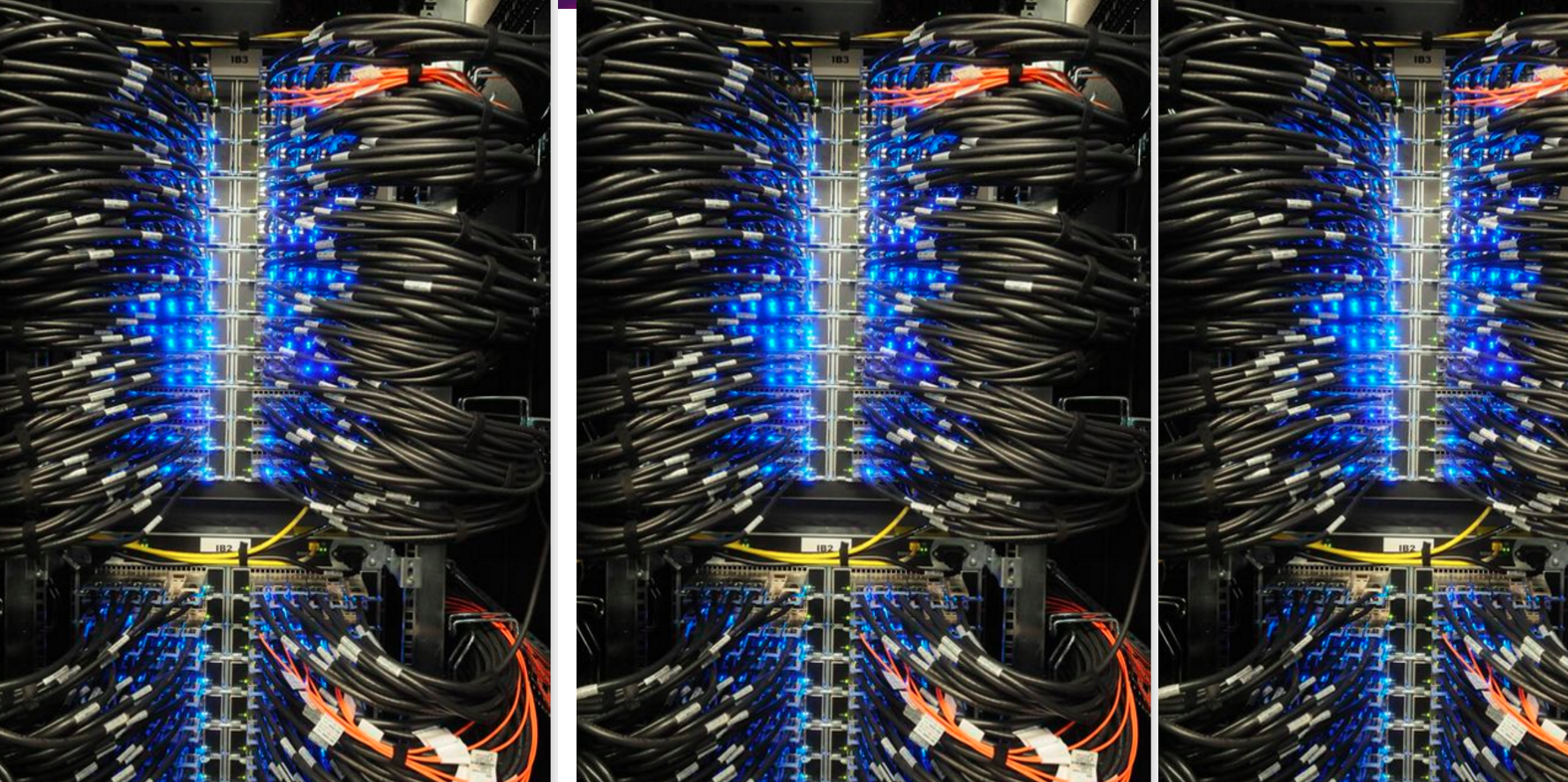
In our recent live SNIA Network Storage Forum webcast, “Next-generation Interconnects: The Critical Importance of Connectors and Cables” provided an outstanding tutorial on the latest in the impressive array of data center infrastructure components designed to address expanding requirements for higher-bandwidth and lower-power. They covered common pluggable connectors and media types, copper cabling and transceivers, and real world use cases. If you missed the live event, it is available on-demand.
We ran out of time to answer all the questions from the live audience. As promised, here are answers to them all.
Q. For 25GbE, is the industry consolidating on one of the three options?
A.
The first version of 25 GbE (i.e. 25GBASE-CR1)
was specified by the Ethernet Technology Consortium around 2014. This was
followed approximately two years later by the IEEE 802.3 versions of 25 GbE
(i.e. 25GBASE-CR-S and 25GBASE-CR). As a result of the timing, the first 25 GbE
capable products to market only supported consortium mode. More recently
developed switches and server products support both consortium and IEEE 802.3
modes, with the link establishment protocol favoring the IEEE 802.3 mode when
it is available. Therefore, IEEE 802.3 will likely be the incumbent over the
long term.
Please note that there is no practical difference between Consortium vs. IEEE
802.3 for short reaches (<=3m) between end points, where a 25G-CA-N
cable is used. The longer cable reaches above 3m (CA-25G-L) requires the
IEEE 802.3 modes with forward error correction, which adds latency. The
CA-25G-S type of cable is the least common. See slide 16 and slide 17
from the presentation.
Q. What's the max DAC cables (passive and/or active) length for 100G PAM4?
A. The IEEE P802.3ck specification for 100 Gb/s/lane copper cable PHYs targets a reach of at least 2 meters for a passive copper cable. Because the specification is still in development, the exact reach is still being worked out. Expect >2 meters for passive cables and 3-4 meters for active cables. Note that this is a reduction of reach from previous rates, as illustrated on slide 27, and that DAC cables are not for long range and generally used for very short interconnections between devices. For longer reaches, AOC cables are preferred.
The passive copper cable length is primarily driven by the performance of the SERDES in the host (i.e. switch, server, FPGA, etc) and the construction materials of the cable assembly. Active copper cables (ACCs or AECs) use several different methods of signal conditioning to increase the cable reach; more sophisticated solutions have greater reach, greater latency and greater cost. See slide 35.
Q. What's the latency difference between active and passive DAC (PAM4 encoding)?
A. Passive copper cables do not contain signal conditioning electronics. Active copper cables (ACCs or AECs) use several different methods of signal conditioning to increase the cable reach; more sophisticated solutions have greater reach, greater latency and greater cost. See slide 35. A simple active cable may use one or more linear equalizer IC where as a complex cable uses a full retimer that may use FEC logic embedded inside.
For 50G PAM4 rates, the difference in one-way latency between a passive copper cable and a simple active copper cable is ~20 nsec. The difference between a passive copper cable and a complex active copper cable could be as high as ~80 nsec.
Q. Can you comment about "gearbox" cables (200G 4lane (@56G) to 100G 4 lane (@28G)?
A. A few companies are supplying cables that have 50G PAM4 on one end and 25G-NRZ on the other with gear box. We see it as a niche; used to link new to older equipment.
Q. Showing QSFP instead of OSFP on slide 29 in the image at the top right?
A. Good catch. That was a mistake on the slide. It has been corrected. Thanks.
Find a similar article by tags
Networked StorageLeave a Reply
Cabling, Connectors and Transceivers Questions Answered
Nov 9, 2021

Leave a Reply
Revving Up Storage for Automotive
Nov 8, 2021

Each year cars become smarter and more automated. In fact, the automotive industry is effectively transforming the vehicle into a data center on wheels. Connectedness, autonomous driving, and media & entertainment all bring more and more storage onboard and into networked data centers. But all the storage in (and for) a car is not created equal. There are 10s if not 100s of different processors on a car today. Some are attached to storage, some are not and each application demands different characteristics from the storage device.
The SNIA Networking Storage Forum (NSF) is exploring this fascinating topic on December 7, 2021 at our live webcast “Revving Up Storage for Automotive” where industry experts from both the storage and automotive worlds will discuss:
- What’s driving growth in automotive storage?
- Special requirements for autonomous vehicles
- Where automotive data is typically stored?
- Special use cases
- Vehicle networking & compute changes and challenges
Start your engines and register today to join us as we drive into the future!


Leave a Reply